 Contact Us
 TurnaSure DTIs can be installed in various ways to suit your needs and your project!
Structural DTI installation for ASTM F959 and F959M DTIs, and other worldwide structural bolt and DTI standards
Traditional TurnaSure DTIs can be installed in any one of three different ways (see illustrations below). Method #1 is recommended for applications with 3 or more plies and/or when very large bolts are used as it assures that any undesired movement in the steel plies has not trapped a long bolt. Otherwise ALL methods are good depending on the erector's preference. TurnaSure curved protrusion DTIs can be installed under the nut WITHOUT the need or cost of a hardened washer. Assembling the DTI directly under the nut is satisfactory on standard length bolts in the usual two or three ply connections when hardened DH or 2H nuts are used. One advantage of using DTIs on the ‘turned element’ (nut) side is allowing the tightening tool operator to inspect their work as each assembly is tightened.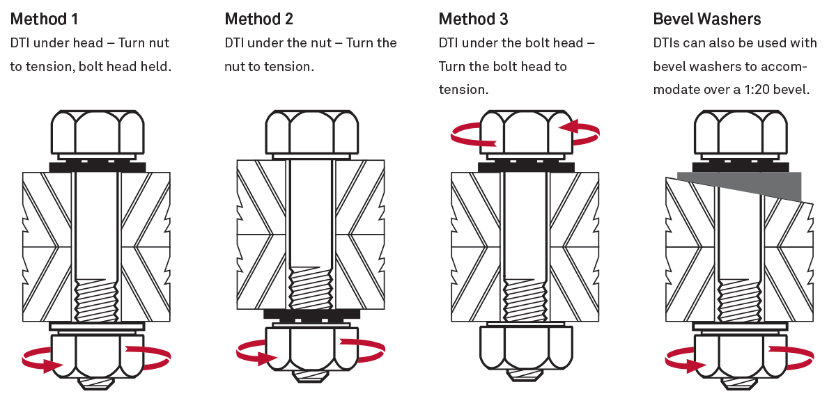
To download the installation instructions right for your structural application, click on the appropriate manual link on the rightbelow, or you may contact us and we will send it to you by mail.
SAE Type Tension Indicating Washers described in SAE J2486
Most often, the DTI (or TIW) is placed under the head of a matching Grade 5 or Grade 8 (or Class 8.8 or 10.9) cap screw. The nut is turned to tighten the cap screw, and the resulting clamping force begins to flatten the protrusions. Other acceptable methods are shown below, including tightening into a tapped hole. The DTI can be fully flattened, or the 0.010in/0.250mm feeler gauge can be used as a "no-go" inspection tool inserted between two adjacent protrusions. The notches on the circumference of the TIW show where the gaps are located to ease inspection.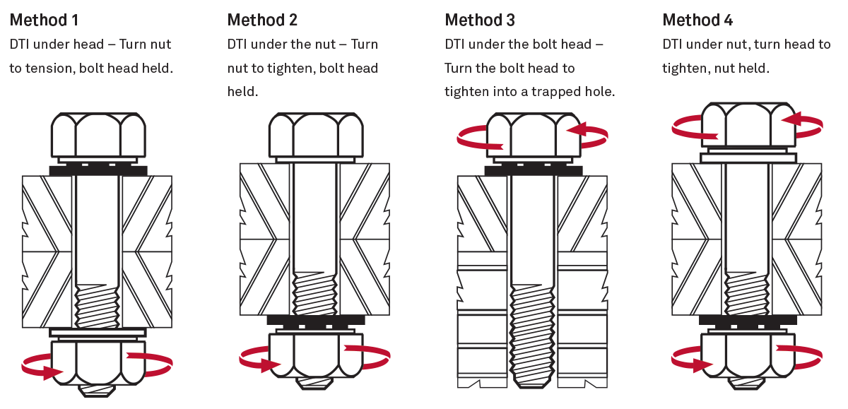
DTIs for studs on gasketed flanges
DTIs for studs on gasketed flanges are usually assembled under the nut with the protrusions facing the bearing surface of a hardened washer or hardened heavy hex nut. Then the tightening torque energy is applied to the nut on the other end of the stud to initiate tightening. (See Assembly Method 1) The increasing clamping force directly correlates to flattening of the protrusions, which reduces the gap. The "target gap" is pre-selected from the Test Certificate and Load-Gap Chart that is available for each production lot of DTIs. These test reports clearly depict which gap dimension corresponds to the required tension or clamping force required for the particular application. For example, if a 0.010in gap provides the required load of 50,000 lbs., (60% of yield for a 1 1/8in B7 stud), then when the gap between the DTI and the nut has been reduced to just less than 0.010in the required clamp load has been achieved.
DTIs for Anchor Bolts
DTIs for anchor bolts, studs, and rod are assembled under the nut, with the protrusions facing ‘up’ bearing on a through-hardened washer over which the nut is placed. As the nut is turned to stretch the anchor bolt, the gap of the DTI is reduced proportionally to the tension being induced in the anchor. One of our most commonly used DTI designs has been specially made so that once the DTI is completely flat, the desired level of tension or clamping force is reliably present in the anchor bolt, stud, or rod.Contact TurnaSure today for more information, availability and quotes.